The Camel Goes Kite Surfing
Presented at the O'Reilly Perl Conference 5, July 23-27 2001
This paper describes the architecture and implementation of a tool written in Perl to assist in the design and construction of high performance power kites. It introduces the sport of traction kiting and describes the desired features of the kites used. It highlights the need for and requirements of such a tool, in particular emphasising a level of adaptability which will allow considerable experimentation and reworking of the kite design. It demonstrates an approach which uses Perl's flexibility to easily build complex models of the 3D information representing a kite from relatively simple parametric algorithms. It shows how the Template Toolkit[1] is used to present the resultant data model in different formats for 3D visualisation via the POV-Ray[2] ray tracing program, and for generating 2D cutting plans as PostScript[3] files.
Over the past decade kite traction has evolved as a new and exciting variation of one of the World's oldest pasttimes. In its general form, kite traction describes any kind of activity in which large and powerful kites are used for propulsion: to pull a rider along on a mountain board, snowboard, surfboard or specially designed 3-wheel kite "buggy". Kite surfing[4] in particular has captured the attention of kite fliers, surfers, windsurfers and other extreme sportsmen and women as the latest and greatest way to get an adrenaline fix. Dedicated exponents of the sport can be seen "boosting big air" - allowing themselves to be pulled up into the air by the kite - often rising tens of feet upwards while pulling off incredible tricks with typically bizarre names. In a little over 2 years, kite surfing has grown from a novel idea to a glamorous, multi-million dollar sport boasting a professional competition circuit, increasing television coverage and a host of dedicated companies providing specialist equipment.
Kite surfing brings with it a number of challenges for the designers of the traction kites that power the sport (i.e. the author, in his copious spare time). The kites must be powerful but also highly maneuverable so that they remain easy to handle in a wide range of wind conditions. They should be aerodynamically efficient (i.e. high coefficient of lift and low drag) to allow surfers to make good upwind and to make possible big airs with (hopefully) smooth landings. Perhaps the hardest design challenge is that the kites must float and be relaunchable from water. Even the best kite surfers take regular dunkings and need to be able to get themselves and their kites out of the water to avoid a long swim back to shore.
This paper describes how Perl has been used to help design, visualise and construct a new kind of traction kite aimed particularly at the kite surfing market. It will be organised as follows. The first section will investigate the current state of the art in computer aided design for traction kites, look at the motives for undertaking this project and identify the key requirements of a design tool. The following sections will present the solution, looking first at how the 3 dimensional model was built in memory using simple mathematical constructs and regular Perl data structures. It will then focus on how the data model was presented in different formats by use of the Template Toolkit. These formats were primarily POV-Ray scene description files for 3D visualisation of the kite during the design phase, and PostScript files which contained the lifesize cutting plans for the subsequent construction of the kite. The final section will review the state of the project and summarise the benefits of using Perl and employing these particular techniques.
Kite design is something of an arcane subject area but not one without some considerable interest from dedicated amateurs and commerical organisations. The Foildesign mailing list[5] has over 200 subscribers, many of whom are actively designing and building kites using one particular computer aided design tool. Foilmaker[6] is a GUI based tool for designing traction kites of the ram-air inflated "soft foil" variety (i.e. without spars), very similar in concept to modern parachute or paragliger canopies. It boasts a number of advanced features and can be used to create a wide range of different kite designs within this particular class. It is available as a freeware program but not as Open Source as it relies on some proprietary code which the author does not have the rights to distribute or the time and resources to re-implement. Furthermore, the program is only available for the Microsoft Windows platform.
Needless to say, the lack of source code makes it impossible to extend the program to include new features or experiment with entirely new kinds of kite based on different fundamental design principles. It is a great shame that this is the case as Foilmaker is an otherwise excellent program. With no other kite design software readily available the only option left open was to build a bespoke tool from scratch.
The requirements of such a tool were determined to be as follows. Firstly, the tool should facilitate a completely parametric approach to design. That is, it should be possible to describe every feature of the kite using a set of variable parameters, ideally numbering as few as possible. Typical parameters of a kite's design are the surface area, wingspan (distance from wingtip to wingtip), chord length (distance from leading edge at the front to trailing edge at the back), aspect ratio (ratio of the wingspan to mean chord length), archform (curvature of canopy when viewed from the front), and so on. This precise parameteric approach was considered necessary in order to contribute some degree of scientific validity to testing different configurations. For example, we would like to be able to make two kites to be flown side-by-side which differ in only one parameter such as aspect ratio, with all others remaining constant. Only then can we hope to make valid observations relating to the perceived effects of changing a particular variable.
Secondly, it should allow us to visualise the design of the kite for a given set of parameters. Because kite design is still very much a black art, it often relies on hunches based on previous experience rather than any hard and fast design rules. It is therefore invaluable for the designer to be able to see what a kite will look like without having to actually go and make it. So although it is exceedingly difficult to describe the knowledge of an experienced kite designer in any tangible way, there does exist an acquired ability to have a reasonably accurate feeling for what is or isn't likely to work well. In showing a designer what a particular kite will look like early on in the design phase, we can hope to capitalise on that knowledge and eliminate some of the no-hopers, even if we can't say for sure in advance what it is that makes a good or bad kite design.
The third important requirement is to be able to take a satisfactory design and automatically generate cutting plans for the construction of the prototype kite. Measuring and marking up the pattern for such a kite is quite possibly the most time consuming and error prone activity in the entire construction process. By automating this step we can significantly reduce the time taken to build a kite from scratch and also eliminate errors that otherwise typically appear when it's too late to correct them (i.e. when the fabric has been cut and the kite sewn together).
The final major requirement is that the tool should be highly adaptable. Given that we plan to make some radical departures from traditional traction kite design, we can expect to make a number of bad decisions, follow blind alleys and totally change our minds several times along the way. We must be able to quickly adapt the tool and iteratively rebuild elements of it as a key part of the design process. As we have new ideas and gain further insights into the exact kind of traction kite that we want to build, we should be able to change the program to model the new design quickly, easily and without fuss.
The first task is to build a data model in memory which in some way represents the form of the kite. To achieve this, the specific style and architecture of the kite must first be decided and algorithms developed for modelling it in parametric form.
In the broadest possible terms, kites fall into two general categories: single or multiple line. Single line kites are primarily used for decorative purposes and although they can easily generate enough lift to be useful for lifting a camera (e.g. for aerial photography) or even a person, the fact that they are tethered by a single line generally limits them to flying at a fixed position in the sky.
On the other hand (or more accurately, in both hands), kites with multiple control lines can be steered around the sky by apply more pressure to one line than the other. Pulling on the line in the left hand causes the kite to turn to the left, pulling on the right, to the right. Steerable kites generally have 2 lines attached to handles, one of which is held in each hand, or 4 lines connected to a flying bar or handles (2 to each handle), again held in both hands, or possibly attached to a waist or sit-in harness. Kites like these can be flown for simple pleasure, for competitive purposes (e.g. "precision" to demonstrate control, "ballet" choregraphed to music, or "freestyle" performing tricks) or to generate serious pulling power for kite traction sports. This last category is of primary relevance to this paper and the kites used for this are typically soft foils or single skin kites with spars or inflated tubes. In all cases, they have multiple control lines.
Soft foils are "baggy" kites. The wing is constructed as a series of pockets which are ram-air inflated by the wind passing through a gauze or vents on the leading edge. When inflated they form an airfoil section due to the precise shaping of the "bags" which then generates lift via Newton's third law (in essence, the wing diverts air downwards and for every action there is an equal and opposite reaction, or in other words, lift). The canopy is kept in shape by a large number of bridle lines which spread the load across the canopy and prevent it (most of the time) from folding up into a big, floppy bag of fabric. As mentioned previously, they bear close resemblance to modern parachute or paraglider canopies. They are convenient to transport and use, folding up into a small volume and opening out for use in a matter of seconds.
At the other end of the spectrum there are single skin "sticky" kites which use carbon fibre spars to stretch the fabric taught to hold a particular shape. These kites are typically more efficent for the simple reason that they are lighter. In addition to the fabric and bridle lines, a foil also contains a large volume of enclosed air which adds a significant mass to the kite. It is Newton again who tells us in his second law (force = mass x acceleration) that a heavier object will require more energy to set moving. Single skin kites have no enclosed volume of air to transport and thus can acheive greater acceleration for a given force, which in this case is provided by the wind.
Unfortunately, sticky kites suffer from scalability problems. To increase a sparred kite to a size large enough to generate serious traction power (typically a wingspan of 3-5 metres or more), the thickness of the spars required to adequately support the structure increases to the point of being too heavy to fly in anything but the strongest wind. The closest analogy to something this large would be a hang glider. Common sense dictates that something that large and heavy shouldn't be tethered and flying around directly over peoples' heads, as kites typically are. Soft kites are much safer in this respect but they have their own limitations. The problem most relevant to kite surfing is that foils are generally not relaunchable from water, although some designs are now incorporating one-way valves to seal the air within the kite, allowing them to float on, rather than fill with water.
It is beyond the scope of this paper to delve any deeper into the relevant strengths and weaknesses of the different design styles. Suffice it to say that the key goal is to attempt some hybridization of the two extremes and determine if there is a "better of both worlds": a single skin hybrid which has the benefits of a sparred kite with the scalability of a soft foil. A number of hybrid kites have appeared in recent years such as the Wipika[7] and Flexifoil Nexus[8]. These have provided particular inspiration by their use of high-pressure inflatable tubes as a substitute for spars or ram-air pockets. One important benefit is that these tubes allow the kites to float on water making them more easily relaunchable.
This was taken as a suitable starting point. The kite would consist of a leading edge formed from an inflatable tube with a single skin extending back to the trailing edge. This would be held in position by a number of vertical ribs placed across the span of the kite, with careful shaping of the seams ensuring that the fabric naturally billowed into the correct airfoil form. Viewed from the front (archform), the kite would be arched to provide stability and increase spanwise structural integrity. Looking from above (planform), the wingtips would be swept back to reduce the wingtip vortices associated with drag. The rib profiles would have spars running chordwise from front to back (leading to trailing edge) to add support to the kite structure, thereby reducing the number of bridle lines required that otherwise add to the complexity, construction time and aerodynamic drag of the kite. See figure 1.
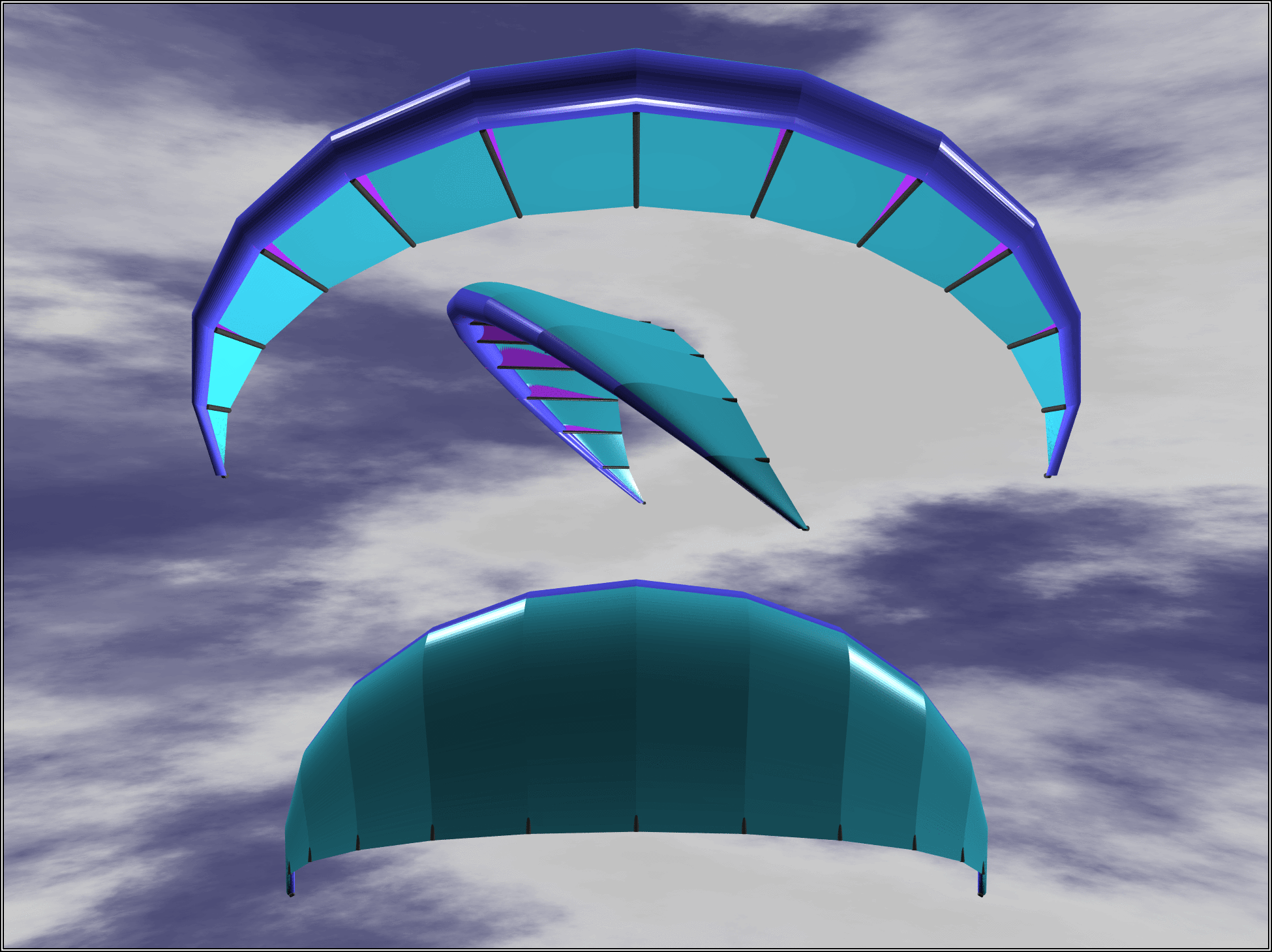 |
| Figure 1: Oxygen: Single Skin Hybrid Traction Kite |
The essence of the problem is then to design and build a self-supporting 3 dimensional object from 2 dimensional fabric sheets. This would undoubtedly be an insurmountable task for a human designer without the aid of computer. The rest of this paper will concentrate on how Perl was used as the implementation language, and the Template Toolkit (itself written in Perl) was used as a presentation mechanism to achieve this.
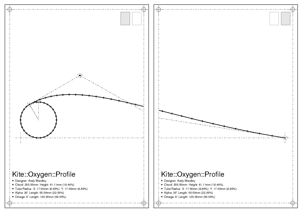
To generate a data model of this kite, the first approach was to define the cross-section airfoil shape. This is shown in figure 2.
 |
| Figure 2: Cross Section Airfoil Profile |
The leading edge tube can be represented in the 2 dimension cross section as a uniform circle. Calculating points around a circle for a given radius is a simple matter of sine and cosine mathematics. The radius of this tube is defined as a percentage of the chord length, that is, the length of the profile from leading edge to trailing edge. The calculation then looks something like this:
use constant RADIANS => 57.29;
my $chord   = 850;            # chord length in mm
my $radius  = 7;              # 7% of chord length
my $npoints = 30;             # 30 points around circle
my $dtheta  = 360 / $npoints; # degrees per point
my @circle;                      # points around circle

for (my $theta = 0; $theta < 360; $theta += $dtheta) {
  my $trad = $theta / RADIANS;
  push(@circle, [ $radius + sin($trad) * $radius,
      $radius + cos($trad) * $radius ]);
}
A Bézier curve is used to represent the kite skin which extends back from the leading edge tube to form the airfoil section. A Bézier curve can be entirely defined by four points: the start and end points and two further points in between which affect the shape of the intermediate curve. The control points for the Bézier curve are shown in figure 2 as the ringed dots connected by dashed lines. The first point is positioned on the leading edge circle at a particular angle (alpha) counter-clockwise from vertical. The second control point is then calculated to lie on the line which is at the tangent to the circle at that point. The distance of the control point along this line is another parameter (alpha length) expressed as a percentage of the chord length. The last point is placed at the rightmost end of the profile (trailing edge). The penultimate point is positioned on a line extending at an angle (omega) from horizontal and distance (omega length) from that final point. The upshot of this is that the five parameters: radius, alpha, alpha length, omega, and omega length, collectively define a particular profile shape which scales proportionately to the chord length. Thus it is possible to define one profile shape for a kite which is used many times at different points on the kite and scaled to different sizes.
A quick search of CPAN[9] revealed nothing suitable for calculating points along a Bézier curve, but a copy of Graphic Gems V[10] had the answer in the form of a paper entitled "Quick and Simple Bézier Curve Drawing". An implementation in C was provided which was quickly and painlessly transcribed to Perl, thanks to Perl's ability to look and feel like C when it has to. The core code for solving Bézier curves is no more than a few dozen lines and in a little less than an hour, the newly crafted Math::Bezier module had been written, documented and uploaded to CPAN (with appropriate credit to the original author, of course).
With this module in place to abstract away the complexity, solving the Bézier curve for the kite's profile is trivial. A Math::Bezier object is created to represent the form of the curve, with 4 sets of (x, y) coordinates being passed as constructor parameters to represent the control points. In the following example we assume that these values have been calculated from the alpha/omega parameters, neatly sidestepping the simple but tedious detail in those particular calculations.
use Math::Bezier;

# assume $x1, $y1 . . $x4, $y4 calculated from alpha/omega
my @control = ($x1, $y1, $x2, $y2, $x3, $y3, $x4, $y4);
my $bezier  = Math::Bezier->new(@control);
Finding the (x, y) coordinates of a set of points evenly spaced along the curve is a simple matter of calling the curve() method, passing the number of points required. The method returns a list or reference to a list (depending on calling context) containing a list of (x, y) values.
my @curve = $bezier->curve($npoints);
There is now enough information to fully calculate the shape of an airfoil profile according to the original 5 parameters. The single chord length parameter then defines the overall size of a particular profile instance, with all other parameters being expressed or calculated relative to this value. These calculations are then encapsulated in a module which nicely hides the implementation detail behind a simple interface.
use Kite::Oxygen::Profile;

my $profile = Kite::Oxygen::Profile->new({
    chord   => 850,     # 850 mm chord length
    radius  => 7,       # l/e tube radius: 7% chord
    alpha   => 30,      # alpha angle: 30 degrees
    alen    => 22,      # alpha length: 22% chord
    omega   => 9,       # omega angle at t/e: 9 degrees
    olen    => 50,      # omega length: 50% chord
});
Instantiation of an object of this class includes the calculation of all the points on the circle and Bézier curve based on the parameters provided. The points around the circle and along the Bézier curve can then be retrieved via simple method calls.
$points = $profile->circle();
$points = $profile->curve();
A method is also provided for returning a concatenated list of all points on the profile, including those in the circle and curve.
$points = $profile->points();
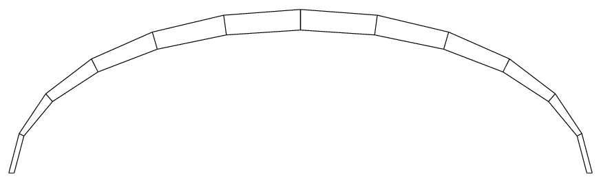
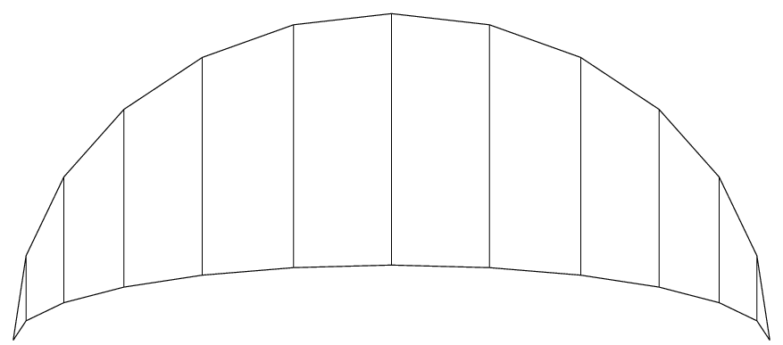
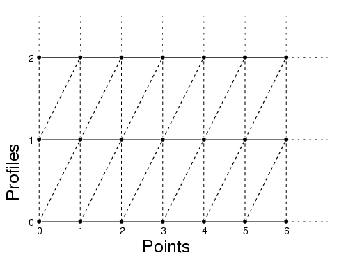
Building a 3D model from a set of these 2D profiles is a relatively straightforward matter of determining the required number, size and position of profiles and then transforming them into position with some simple trigonometry. To achieve this, we define an archform (figure 3) and a planform (figure 4) which describe the shape of the kite when viewed orthogonally from the front or above, respectively.
 |
| Figure 3: Archform (front view) |
 |
| Figure 4: Planform (top view) |
These forms are defined as elliptical curves which can be expressed by two values, the major and minor radii. For the archform, the minor radius is the height of the middle of the canopy above the wingtips. For the planform, it represents the distance of the middle (nose) of the kite in front of the wingtips, or in other words, the degree to which the wingtips are swept back. In both cases, the major radius is half the total wingspan of the kite.
my $arch = Kite::Oxygen::Archform->new({
    width     => 5000,    # 5.0m wingspan
    height    => 1000,    # 1.0m height
    panels    =>   12,    # 12 panels
});

my $plan = Kite::Oxygen::Planform->new({
    width     => 5000,    # 5.0m wingspan
    sweep     => 1500,    # tips 1.5m behind nose
    max_chord => 1000,    # 1.0m chord length at nose
    min_chord =>  300,    # 0.3m chord length at tips
    panels    =>   12,    # 12 panels
});
From the archform and planform it is possible to calculate the position, length, height and orientation of the required profiles. These are shown on figure 3 as the short lines radiating outwards, and on figure 4 as the vertical lines joining the leading edge at the top of the figure to the trailing edge at the bottom.
For the sake of brevity, we won't dwell any further on the underlying algorithms and mathematics involved in the 2D/3D modelling stages and will instead summarise by showing how this entire process has been encapsulated into a Perl module.
use Kite::Oxygen;

my $kite = Kite::Oxygen->new({
    title      => 'Oxygen Test #16',
    designer   => 'Andy Wardley',
    wingspan   => 5000, # width from tip to tip
    height     => 1000, # height of archform
    sweep      => 1500, # distance of tips being nose
    max_chord  => 1000, # maximum chord length (nose)
    min_chord  =>  300, # minimum chord length (tip)
    panels     =>   12, # number of panels
    profile    => {         # profile characteristics:
        radius =>    7, # l/e tube radius: 7% chord
        alpha  =>   30, # alpha angle: 30 degrees
        alen   =>   22, # alpha length: 22% chord
        omega  =>    9, # omega angle at t/e: 9 degrees
        olen   =>   50, # omega length: 50% chord
    }
});
Instantiating an object of the Kite::Oxygen class ('Oxygen' being the working title for this particular kite project) causes all the form calculations to be made and a set of internal profile objects to be created which are correctly transformed to their intended positions in 3 dimensions (i.e. the 'z' dimension is added to compliment 'x' and 'y'). The constructor thus returns an object which represent a complete model of the 3D data that comprises the kite design.
This is an example of the "Facade" design pattern[11]. The kite is modelled as a number of smaller components (e.g. profiles, archform, planform), each of which may contain further complex elements (circles, curves, etc) and specific configuration details. The Kite::Oxygen module is a simple front-end which abstracts away the more complex underlying detail of the sub-systems. It hides away the internal wiring, making it easier to instantiate complex objects via a single interface without sacrificing the lower level modularity of the system. If, for example, we should decide to write a new module to calculate the archform in an entirely different fashion, then it should be possible to slot the new module directly into the system in place of the old. Thus, the 'archform' parameter can be used to provide a class name or a pre-instantiated object reference which should be used to represent the archform in place of the default Kite::Oxygen::Archform class.
use Kite::Oxygen;
use My::New::Archform;

my $kite = Kite::Oxygen->new({
    archform   => 'My::New::Archform',
    wingspan   => 5000, # width from tip to tip
    sweep      => 1500, # distance of tips being nose
    .
    .
    .
});
With the complete data model of a kite directly accessible via the Kite::Oxygen module, we can now consider how the various different output formats, or more generally, "views", of this model are generated. Here we can identify another familiar design pattern, the Model/View/Controller. In essence, this describes the practice of separating a system into a model to represent the underlying data (e.g. the 3D model of the kite), a number of views to present the model in a particular way (e.g. PostScript, POV-Ray output formats) and controllers which manipulate or modify the data model (bits of Perl code implementing the various mathematical algorithms). One key benefit of this approach is that it allows multiple views of the same model to be easily generated (model/view multiplexing). Another important factor is that views and/or the model itself can be modified in isolation with little, if any, impact on the other elements. This is especially important for a system which is likely to undergo major changes many times during its lifetime.
The Template Toolkit is used to acheive this clear separation of concerns. There are numerous other fine modules available from CPAN for template processing, many of which could be used to similar ends. However, the author is naturally enamoured to this particular module which, as the presented solution should hopefully demonstrate, provides many useful features for this kind of task.
Starting with a very simple example, a Template object is created to act as the Template Toolkit processor. Numerous configuration options can be provided, one of which is INCLUDE_PATH. This allows one or more directories to be specified where the toolkit should look for template files:
use Template;

my $tt = Template->new({
    INCLUDE_PATH => '/home/abw/kites/oxygen/templates',
});
The '$tt' object is then directed to process a template
file (which should reside in the INCLUDE_PATH directory) via the
process() method. In addition to the name of the template file, a
reference to a hash array containing template variable definitions is
also passed. An optional third argument can be used to specify a
filename for the generated output, otherwise it is directed to STDOUT.
my $vars = {
    kite => $kite,      # object reference created earlier
};

$tt->process('example', $vars)
    || die $tt->error();
This illustrates one of the particular strengths of the Template
Toolkit: the '$kite' object reference can be assigned
directly to the template variable, 'kite', leaving the
Template Toolkit to worry about calling the right methods and/or
inspecting the underlying data in the correct fashion. The example
template below shows a number of directives (embedded within the
character sequences '[%' and '%]') which
access various different parts of the data model. In some cases, these
are object methods (e.g. 'kite.profiles' =>
'$kite->profiles()') and in others they are hash
elements (e.g. 'p.x' => '$p->{x}'), but
from this perspective it makes no difference. We would like to think of
that as an underlying implementation detail in the model which is
subject to change.
[% kite.title %] designed by [% kite.designer %]
Wingspan: [% kite.wingspan %]
  Height: [% kite.height %]
   Sweep: [% kite.sweep %]

[% kite.profiles.size %] profiles:
[% FOREACH p = kite.profiles %]
  #[% p.n %] at ([% p.x %], [% p.y %])
[% END %]
The output generated from processing this template then looks something like this:
Oxygen Test #16 designed by Andy Wardley
Wingspan: 5000
  Height: 1000
   Sweep: 1500

7 profiles:
 #0 at (0.29, 1249.92)
 #1 at (647.28, 1207.3)
 #2 at (1250.17, 1082.41)
 #3 at (1767.87, 883.77)
 #4 at (2165.11, 624.92)
 #5 at (2414.83, 323.48)
 #6 at (2500, 0)
The toolkit uses the dot operator '.' for manipulating
complex data and it "Does the Right Thing" depending on the underlying
data type. In fact, you can pass in almost any kind of Perl data as a
template variable, including simple scalars, hash arrays, list
references, objects or sub-routines, and expect it to work without any
further intervention. The specific details of how a piece of data is
represented is something for you to worry about when you're building the
model, not when you're trying to view it.
This is known as the "Uniform Access principal" as promoted by Bertrand Meyer[12]. It makes life easier in the short term because it helps to create a clear separation of concerns between data, application and presentation elements. You can wear a programming hat on one day and an HTML designer (or PostScript junky, POV-Ray guru, etc.) hat the next. Maybe you have (or would like to have) a project where different people wear their different hats on a full-time basis. If you have to worry about breaking presentation templates when you change the data model, or vice versa, then you are wearing more than one hat at a time, or in other words, having to think about two things at once.
It also makes life easier in the long term because both the model (data) and the views (templates) are conducive to change with minimal cross-interference. We should be able to implement a kite model as a hash array one day and change it to an object based on a blessed list reference the next, without requiring any change in the presentation templates.
The Persistance of Vision [tm] Ray Tracer (POV-Ray) is a free and Open Source program which implements an exceptionally powerful technique known as ray tracing for generating photo-realistic images of 3D scenes. The program emulates nature by calculating the paths of millions of imaginary rays of light bouncing around a scene, reflecting off imaginary objects and eventually ending up in an imaginary camera in which the completed picture of the scene is fully developed.
Unfortunately, ray tracing is not a speedy process and the imaginary photons emulated by the program fall somewhat short of travelling at light speed. It's not unusual to wait minutes, hours, days or longer for a complex ray tracing scene to be processed. Fortunately, the kind of scenes being traced for this application are simple enough that the process completes in a matter of seconds.
There are numerous other approaches for creating 3D visualisations of a data model, with VRML (Virtual Reality Markup Language)[13] possibly being the most viable alternative (and that employed in Foilmaker). However, POV-Ray was chosen for the entirely pragmatic reasons that, unlike VRML, the author already had the relevant software installed on his computer and was intimately familiar with the scene description language used. The beauty of the model/view abstraction is that we can easily add support for VRML or other formats at a later date.
POV-Ray takes as its input a text file containing a description of the 3D scene written in a special language. The following example shows a simple input file which describes the location and orientation of a camera, two lights, a sphere and a cylinder, both of which are hovering mysteriously above the computer graphics standard checkered floor.
#include "colors.inc"

camera {
    location  <-3, 4, -2>
    look_at   <-2, 1,  2>
}

light_source {
    <-30, 20, -20> color White
}

light_source {
    <30, 30, -10> color White
}

sphere {
    <0, 1, 2> 1
    pigment { color Red }
    finish  { phong 0.8 }
}

cylinder {
    <-4, 1, 1> <-2, 1, 3>, 0.3
    pigment { color Green }
    finish  { phong 0.8 }
}

plane {
    <0, 1, 0>, -1
    pigment {
        checker color Black color White
    }
}
The output of this simple scene is shown in figure 5.
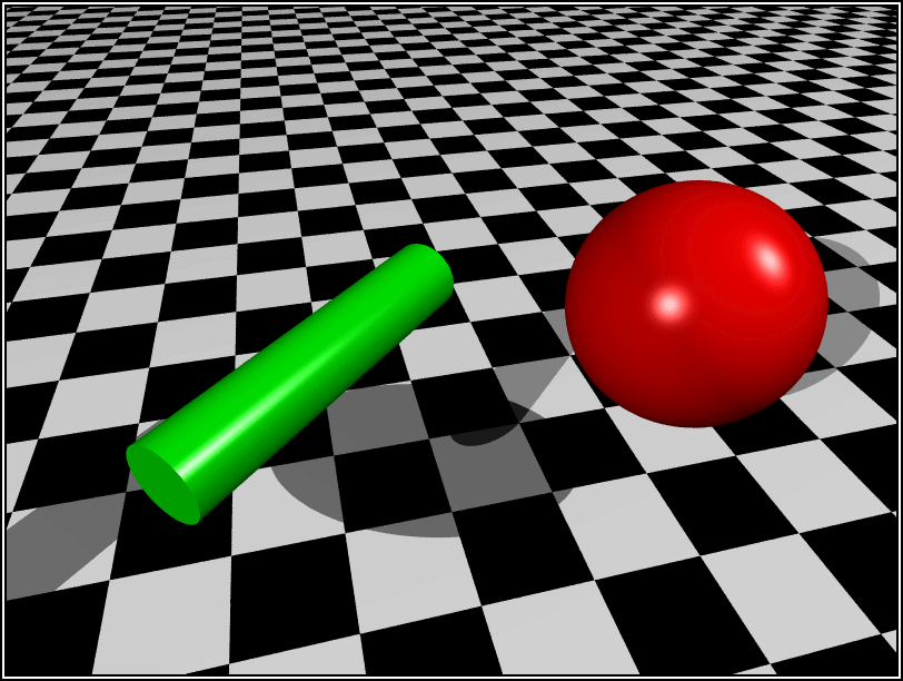 |
| Figure 5: Output of Sample POV-Ray File |
POV-Ray supports a wide range of different graphics primitives such as spheres, cylinders, cones, etc., which can be used to build up more complex objects. Of particular relevance for this project is the mesh primitive. This allows a large number of triangles to be defined, each as a set of 3 <x, y, z> points in space, which collectively form a 3 dimensional "sheet". This is ideal for representing the fabric skin of the kite.
mesh {
    triangle {
        <1, 2, 3>
        <4, 5, 6>
        <7, 8, 9>
    }
    triangle {
        <11, 12, 13>
        <40, 50, 60>
        <49, 64, 81>
    }
    .
    .
    .
}
To generate the mesh data for the kite model, successive pairs of adjacent profiles are selected and their point data iterated through, with two triangles being created for each pair of points.
 |
| Figure 6: Lofting Profiles |
In computer graphics terminology, this technique is known as "lofting", itself a reference to the way in which roofs are constructed on houses. A support frame is first built, which in this case is formed from the upright profiles defining the cross section airfoil (the horizontal lines as viewed from above in figure 6). This is followed by a tiling process which works from front to back of each profile (i.e. left to right in figure 6), effectively "joining the dots" with the equivalent points on its neighbour profiles.
The template used to present the kite data model as a POV-Ray triangle mesh is as follows.
#declare kite = mesh {
[%  # iterate through profiles
    FOREACH thisprof IN kite.profiles;
        NEXT IF loop.first;     # skip first profile
        lastprof = loop.prev;   # previous profile (n - 1)

        # iterate through points in profile
        FOREACH p IN [1..thisprof.points.max];
            l = p - 1;          # index of previous point
            PROCESS triangle    # generate triangle #1
                points = [
                    thisprof.points.$l,
                    thisprof.points.$p,
                    lastprof.points.$l
                ];
            PROCESS triangle    # generate triangle #2
                points = [
                    lastprof.points.$l,
                    lastprof.points.$p,
                    thisprof.points.$p
                ];
        END;
    END;
%]
}
This template declares a custom POV-Ray structure called
'kite', implemented as a triangle mesh.
#declare kite = mesh {
    ...
}
Within that declaration there is a single Template Toolkit directive block containing an outer loop to iterate through the profiles.
FOREACH thisprof IN kite.profiles;
    ...
END;
The special 'loop' variable is a reference to the
iterator (yet another design pattern) which controls the FOREACH loop.
It is used in this case to detect the first iteration of the loop and
skip it:
NEXT IF loop.first;
The iterator also provides access to the immediately previous and next items in the list for convenience. This makes it easy to walk through the profiles in adjacent pairs and also explains why the first profile was skipped - because there was no preceeding profile with which it could be paired.
lastprof = loop.prev;
The inner FOREACH loop iterates through the points in the profiles.
This time a numerical index 'p' is used because we need
to access corresponding points in two different profiles. At the time
of writing, there isn't yet support for running multiple iterators in
lockstep in the Template Toolkit (i.e. simultaneously walking
step-for-step through multiple data sets) so we fall back on the tried
and tested method of keeping track of the current index ourselves. The
variable 'p' holds the index number for the current
point, 'l' the previous one ('p - 1').
FOREACH p IN [1..thisprof.points.max];
    l = p - 1;
    ...
END;
Notice how the index number of the last item in the profile point list
is determined by adding the '.max' suffix to the
'thisprof.points' variable reference. Although the data
returned by 'thisprof.points' is currently implemented as
a simple, unblessed list reference, the Template Toolkit provides
numerous "virtual methods" like this which allow unblessed data to
masquerade as objects. This is the Uniform Access principle at work
again, with the purpose of making our templates less fragile to
underlying changes in the data model. At some point in the future,
'thisprof.points' might instead return an object which
implements its own custom 'max' method. Until then the
virtual methods allow us to treat it like an object, even if it isn't
one.
Finally, at the innermost level, there are two directives to PROCESS
another template, 'triangle', which generates the output
for each individual triangle. An array, 'points', is
passed as a local parameter to this template, containing 3 sets of (x,
y, z) points extracted from the profile data.
PROCESS triangle
    points = [
        lastprof.points.$l,
        lastprof.points.$p,
        thisprof.points.$p
    ];
To fetch an item from an array using a numerical index (the fifth item, for example), the standard approach in the Template Toolkit would be:
[% lastprof.points.4 %]
In this case, the numerical index values are stored in variables
'p' and 'l', so must be prefixed with a
leading dollar, '$', to have their values correctly
interpolated into place. The following example is then equivalent to
the previous one:
[% p = 4; lastprof.points.$p %]
The 'triangle' template to output the point data exists
as a separate template file in the INCLUDE_PATH directory.
triangle {
[% FOREACH p IN points %]
    <[% p.x %], [% p.y %], [% p.z %]>
[% END %]
}
We could equally well define it within the main template as a local BLOCK to avoid having to create a separate file.
[% BLOCK triangle %]
triangle {
[%  FOREACH p IN points %]
    <[% p.x %], [% p.y %], [% p.z %]>
[%  END %]
}
[% END %]
In either case, the template performs the same task of walking through
the 'points' array, printing the (x, y, z) values for
each point, 'p'.
All that remains is to update the POV-Ray source to position the declared kite object somewhere in the scene, textured and transformed according to our particular aesthetic sensibilites.
object {
    kite
    scale 0.3
    rotate <20, 30, 40>
    translate <10, 15, 32>
    pigment { color rgb <0.3, 0.3, 0.8> }
}
We can now process the template as before to generate the complete POV-Ray input file and then feed it into the POV-Ray program for processing. Here's a complete program which does exactly that.
#!/usr/bin/perl -w

use strict;
use Template;
use Kite::Oxygen;

my $ROOTDIR = '/home/abw/kites/oxygen';
my $TTDIR   = "$ROOTDIR/templates";
my $POVDIR  = "$ROOTDIR/povray";
my $TTFILE  = 'povray.tt2';
my $POVFILE = 'oxygen.pov';
my $POVCMD  = "x-povray -I $POVDIR/$POVFILE";

my $tt = Template->new({
    INCLUDE_PATH => $TTDIR,
    OUTPUT_PATH  => $POVDIR,
});

my $vars = {
    kite => Kite::Oxygen->new({ ... }),
};

$tt->process($TTFILE, $vars, $POVFILE)
    || die $tt->error();

system($POVCMD);
The output of the program is shown in figure 1.
PostScript is a device-independant page description language which is the industry standard for printing high-quality text and graphics. It is supported by a wide range of printers and other output devices as well as some excellent free tools such as Ghostview and Ghostscript[14] for on-screen display, manipulating and conversion of PostScript files to various other formats suitable for output to non-PostScript devices.
PostScript is not only a page description language but also a fully functional programming language in its own right. As a stack-based, postfix notation language closely resembling FORTH[15] it is remarkably simple in syntax and structure but can quickly become dense and impenetrable. It is worth noting that the majority of PostScript files are generated by graphics applications and are rarely fit for human consumption. Nevertheless, it is possible to write clean, elegant and even beautiful programs in PostScript, although it possibly takes a special kind of person to appreciate this particular kind of beauty.
Here's a small PostScript program:
%!PS-Adobe-3.0
%%Title: A PostScript Example
%%EndComments

/mm {
    72 mul 25.4 div
} bind def

/cross {
    newpath
    moveto
    -5 mm  0 mm rmoveto
    10 mm  0 mm rlineto
    -5 mm -5 mm rmoveto
     0 mm 10 mm rlineto
    stroke
} def

/ring {
    newpath
    2 mm 0 360 arc
    stroke
} def

/crosshair {
    /y exch def
    /x exch def
    x y ring
    x y cross
} def

10 mm 10 mm crosshair
50 mm 10 mm crosshair

showpage
The program defines a number of procedures: 'mm' converts
PostScript's native coordinate system of points (1/72 inch) to
millimetres; 'cross' draws crossed lines each 10mm long
at the current graphics point; 'ring' draws a circle of
2mm radius around the current graphics point; and
'crosshair' combines the two, drawing both cross and ring
around the current graphics point, to form the familiar crosshair
registration mark. Two of these marks are then made on the page at the
(x, y) coordinates (10mm, 10mm) and (50mm, 10mm) and the
'showpage' command is then issued to display the output
page. This is shown in figure 7.
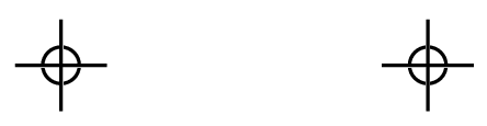 |
| Figure 7: Output of Sample PostScript File |
The Template Toolkit provides a PostScript library which includes
templates that define many useful PostScript procedures like these.
Using the library is a simple matter of adding the system templates
directory, specified during the installation of the Template Toolkit,
to the INCLUDE_PATH, which in this case is
'/usr/local/tt2/templates'.
use Template;
my $tt = Template->new({
    INCLUDE_PATH => [ '/home/abw/kites/oxygen/templates',
                      '/usr/local/tt2/templates' ],
});
The template-generated version of the previous example is then:
[%  PROCESS ps/header
      title = 'A PostScript Example';

    PROCESS ps/crosshair;
%]

10 mm 10 mm crosshair
50 mm 10 mm crosshair

showpage
The library takes care of dependencies between templates, with
'ps/crosshair' automatically loading the
'ps/mm', 'ps/cross' and
'ps/ring' templates to provide the relevant PostScript
procedure definitions.
In addition to providing templates for generating various different marks on the pages, the PostScript library also provides a number of advanced features, one of which is page tiling. This allows an image to be printed which is larger than the paper size for any given printer and have it automatically tiled onto several pages. In this case, the magic happens in the generated PostScript program itself. When the file is sent to a printer, the program queries the device to determine the maximum printable area. It then calculates the size of the image to be printed and splits it up onto as many pages as necessary. It can also add crop marks, registration marks and a small tiling map to the corner of each page to indicate where a page fits within the tiled image set. See figure 8.
 |
| Figure 8: Tiled Profile Output |
This is an invaluable feature for this particular application in which we are routinely generating images larger than any normal paper size. It allows us to concentrate on the task at hand which is generating cutting plans without having to worry about too much of the specific PostScript implementation details. Again, we have acheived a clear separation of concerns, keeping Perl code in one place and complex PostScript code in another.
The master template for generating the lifesize cutting plans of the
cross-section profiles (see figures 2 and 8) is as follows. The first
template directive block loads the PostScript header template via
PROCESS, followed by the various other 'ps/*' templates
which define the procedures required.
oxytiler.tt2:
[% PROCESS ps/header title = "$kite.title designed by $kite.designer";
   PROCESS ps/dot
         + ps/tilemap
         + ps/regmarks
         + ps/text
%]

/tile-path {
    [% PROCESS path %]
} def

/tile-image {
    [% PROCESS image %]
} def

/tile-page {
    [% PROCESS page %]
} def

[% PROCESS ps/tilepage %]
To implement the page tiling, 3 PostScript procedures must be defined:
'tile-path' defines a bounding path for the entire image
- the tiling algorithm uses this to determine how big the image is;
'tile-image' defines the image itself - this is what gets
split up onto multiple pages; and 'tile-page' defines any
per-page elements - these get added to each tiled page and might
include explanatory text, copyright message, crop marks, registration
marks, etc.
In each case, the content of these definitions is separated into individual templates which are PROCESSed into position. Some of the detail in there might get a bit messy so it's probably best for the sake of conceptual clarity to move them out into separate templates.
/tile-path {
    [% PROCESS path %]
} def
With these definitions in place, the 'ps/tilepage'
template is then PROCESSed to insert the PostScript code required to
perform the page tiling. This code performs the calculations to
determine the number of pages required, based on the size of the
'tile-path' path and the printable area of the current
device. It then iterates through the pages printing each one with the
correct section of the larger image, 'tile-image', and
any per-page marks, 'tile-page'.
[% PROCESS ps/tilepage %]
When the main template is processed a reference to a
Kite::Oxygen::Profile object is defined as the 'profile'
variable, optionally accompanied by other variables such as
'map', 'text', 'regmarks',
etc., to control various other aspects of the generated output.
my $kite = Kite::Oxygen->new({ ... });
my $vars = {
    kite    => $kite,
    profile => $kite->profiles->[0],
    map     => 1,
    text    => 1,
};
The content for the definition of the 'tile-path'
procedure is generated in the 'path' template by a simple
traversal along the points of the current profile.
newpath
[% FOREACH p IN profile.points -%]
    [% p.x %] mm [% p.y %] mm [% loop.first ? 'moveto' : 'lineto' %]
[% END %]
The 'image' template which provides the content for the
'tile-image' procedure first strokes the
'tile-path' to draw it on the current page. It also tests
a number of flag variables which are used to control different aspects
of the output. These are the 'construct' variable which
can be set to have construction lines added, and the
'grid' variable which can be set to have a grid laid over
the profile.
tile-path stroke
[%  PROCESS construct IF construct;
    PROCESS grid IF grid;
%]
Each of these "special features" is maintained in its own template file but could just as easily have been directly integrated into the template:
tile-path stroke
[% IF construct %]
  . . . PS to generate construction lines . . .
[% END %]

[% IF grid %]
  . . . PS to generate grid lines . . .
[% END %]
Finally, the 'page' template for generating the
'tile-page' procedure uses a mixture of these two
approaches to display the other non-image elements on each page. It
adds registration marks, a text block and/or a tiling map to each
page.
[% IF regmarks -%]
regmarks
[% END -%]

[% PROCESS textblock IF text %]

[% IF map -%]
tilemap
[% END -%]
By breaking the templates down into smaller components in this way, we
can impose a good degree of structure onto what can otherwise be
something of an ad-hoc process. If, for example, we want to try a
different bounding path, then we can simply copy the
'path' template to a new file (e.g.
'my_new_path') for modification, leaving the original
intact. Testing the new path is then as easy as changing the directive
from:
[% PROCESS path %]
to:
[% PROCESS my_new_path %]
If it doesn't prove favourable, then the directive can easily be changed back again:
[% PROCESS path %]
Alternately, all or part of the template name can be defined in a variable:
[% PROCESS "$item/path" %]
Thus, with just two minor modifications, the main template can be used to generate all the tiled PostScript output required by the program.
/tile-path {
[% PROCESS "$item/path" %]
} def

/tile-image {
[% PROCESS "$item/image" %]
} def
In addition to the profile risers already shown we need to generate
patterns for the upper skin panels. We can now have one set of core
templates for generating profiles ('profile/path' and
'profile/image') and another set for generating the upper
skin panels ('skin/path' and 'skin/image').
The 'item' variable is appropriately primed to designate
the correct templates for generating the path and image for the item
in question and the template is processed. Any other variables, such
as a reference to the profile or skin object in view, are also set as
appropriate.
my $template = 'oxytiler.tt2';
my $kite = Kite::Oxygen->new({ ... });
my $vars = {
    kite => $kite,
    map  => 1,
    text => 1,
};

# generate PS for each profile in kite
$vars->{ item } = 'profile';
my $p = 0;

foreach my $profile (@{ $kite->profiles() }) {
    $vars->{ profile } = $profile;
    $tt->process($template, $vars, "profile_$p.ps")
        || die $tt->error();
    $p++;
}

print STDERR "Generated $p profiles\n";

# generate PS for each skin in kite
$vars->{ item } = 'skin';
my $s = 0;

foreach my $skin (@{ $kite->skins() }) {
    $vars->{ skin } = $skin;
    $tt->process($template, $vars, "skin_$s.ps")
        || die $tt->error();
    $s++;
}

print STDERR "Generated $s skins\n";
The templates for generating the upper panels are equally simple and comparable to those used to generate the profile patterns. The mathematics is encapsulated in the Kite::Oxygen::Skin module which walks through the points on neighbouring profiles mapping the absolute distances betwen 3 dimensional points in space into absolute distance between 2 dimensional points on a flat cutting pattern. Figure 9 shows an example of a generated cutting pattern for an upper skin panel, scaled down to a convenient size and shown without page tiling.
 |
| Figure 9: Upper Panel Output |
The set of modules, templates and scripts that collectively constitute the final tool satisfactorily meet the original requirements. We now have a fully parametric method for generating kite designs, the ability to visualise them in advance and the facility to generate lifesize cutting plans to aid in the final construction. Furthermore, the architecture and design are such that the system is flexible and can be easily adapted in numerous different ways. Future enhancements are likely to include a GUI interface and additional modelling components for constructing kites of different forms.
In this project we have achieved a clear separation of concerns which cleanly partitions application logic and data from presentation elements. We have applied a good degree of structure to the system based around established design patterns and best-practice techniques. These have been the enabling factors in promoting the adaptability of the system, allowing the different data, application and presentation components to be interworked as necessary in a controlled and mangeable way.
In doing so we have crossed the boundaries of 4 different languages: Perl, POV-Ray, PostScript and that of the Template Toolkit. Although almost any computer language could have been used for the programming side of the implementation, there are very few that would have brought the benefits of Perl without other drawbacks. Perl is ideal as a rapid prototyping language because changes can be made to a program in seconds rather than minutes or hours. One doesn't have to worry about memory allocation, type safety, prototype declarations, platform independance and the various other niggling issues that typically get in a programmer's way when they should be concentrating on other matters. This does not imply that Perl's strengths lie only in being a "quick hack" language. It is as capable of expressing programs that are well structured, elegant, efficient and as beautiful as in any other programming language, and in many cases, more so.
The particular strengths of the Template Toolkit, which itself is written in Perl for good reason, are in generating output and integrating existing data or content with it. It is not a general purpose programming language for creating and manipulating data, but a presentation language for displaying it. It is a domain specific language which is optimised for that particular role, just as POV-Ray is tailored for the specification of 3D scenes and PostScript for the description of the printed page.
All that now remains is for the author to allocate some of his copious spare time to using the tool. At the time of writing, a small number of prototype kites have been designed and built. These have proven the program correct in as much that the constructed kites accurately resemble the 3D visualisations generated in the design phase. It is anticipated that in the months and years ahead this tool will facilitate a fruitful iteration process by which the state of the art in traction kite design may in some small way be advanced.
| [1] | Template Toolkit. http://www.template-toolkit.org/ or http://www.cpan.org/modules/by-module/Template/ |
| [2] | Persistance of Vision Raytracer. http://www.povray.org/ |
| [3] | PostScript. http://www.adobe.com/products/postscript/main.html |
| [4] | Kite Surfing. http://www.kitesurfing.com/ |
| [5] | Foildesign mailing list. http://groups.yahoo.com/group/Foildesign/ |
| [6] | Foilmaker. http://fly.to/foilmaker/ |
| [7] | Wipika Kiteboarding. http://www.wipika.com/ |
| [8] | Flexifoil Nexus. http://www.cobrakite.com/nexus.html |
| [9] | CPAN: Comprehensive Perl Archive Network. http://www.cpan.org/ |
| [10] | Graphic Gems V. Edited by Alan W. Paeth, Academic Press Inc., ISBN 0-12-543455-3. IV.8. Quick and Simple Bézier Curve Drawing, Robert D. Miller, p206-209. |
| [11] | Design Patterns. Erich Gamma, Richard Helm, Ralph Johnson, John Vlissides, Addision-Wesley, ISBN 0-201-63361-2 |
| [12] | Object Oriented Software Construction. Bertrand Meyer, Prentice Hall, 1997, ISBN 0-13-629155-4. |
| [13] | VRML: Virtual Reality Markup Language. http://www.vrml.org/ |
| [14] | Ghostview and Ghostscript. http://www.cs.wisc.edu/~ghost/ |
| [15] | Forth: http://www.forth.org/ |